big projects

Back to Back to Back

I’m not quite ready to abandon my upright Stent Panel Workbench for the low, sitting variety.  But I am ready to correct something that’s bugged me ever since I finished the workbench in the first place: the back wing.  It never stayed flat on its own, let alone in plane with the main slab of the bench.  There is clearly some design flaw, even though I allowed for wood movement and ample support with three posts mortised into the slab.  I’ll re-use the wing (which is 86″ x 10″ x 2″ ash) for another project.

IMG_20190722_082238.jpg

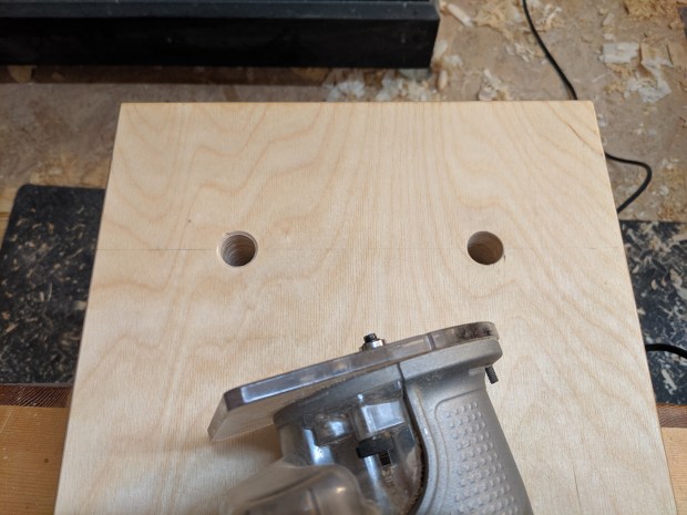
I need more 1″ holdfast holes.

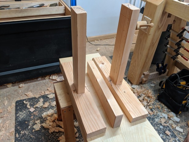
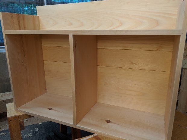
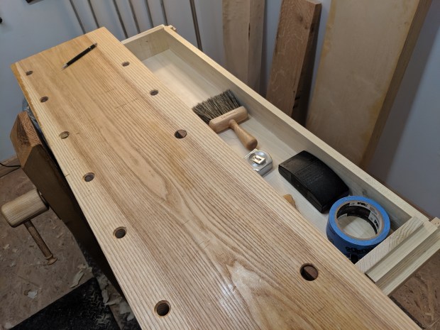
The main slab of the workbench is only 12.5″ wide.  That’s nothing to scoff at, but it’s not nearly enough real estate for tasks like gluing up panels or project assembly.  And there is pretty much no place to set down tools so they are close at hand.  So first up is a tool tray that spans half the area where the wing used to be.  After much deliberation, I’ve approached this a bit like a Dutch tool chest.  Dovetails at the bottom corners for maximum strength, nailed on back.  In 3/4″ poplar, because there was a very nice piece of 1×10 at the home center when I was buying some more 1×12 white pine for general building purposes.

IMG_20190723_081206.jpg

Reasonably consistent color for poplar, and a decent color match to ash once oiled.

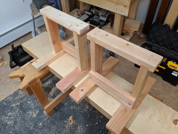
The finished tool tray is just a hair under 37″ wide (the posts themselves are exactly 37″ apart) and 6″ deep.  There is 3.5″ of clearance below the benchtop.  This is plenty for a bench plane on its side and all the other tools I’d like close at hand.  Speaking of which, I decided to attach the tool well to the left side of the bench (the end with the leg vise), which seems like the best place to keep tools at hand.

IMG_20190723_081525.jpg

Because if it can’t fit a hand plane clear of the workbench top, it’s not a good tool tray.

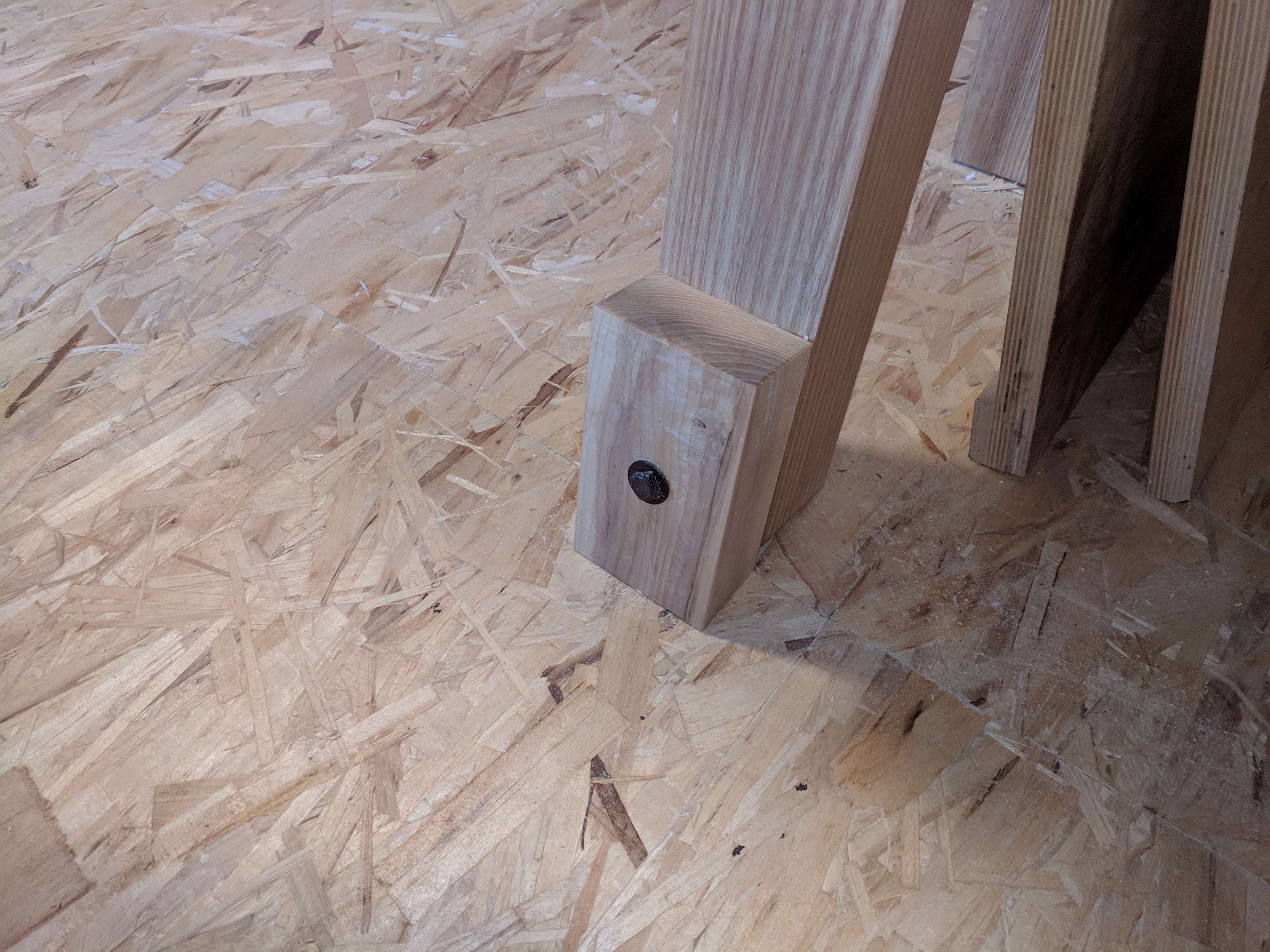
There are a few ways I could have hung the tool tray to the bench.  But the simplest and easiest was to add some runners to the ends so it just hangs on the posts.  The posts are not perfectly in wind, so I clamped the tool tray to the bench and nailed the runners in the right position, rather than squaring them initially and planing them down to fit.  Some small blocks, nailed onto the posts, keep the tray from sliding away from the slab.

IMG_20190724_070658.jpg

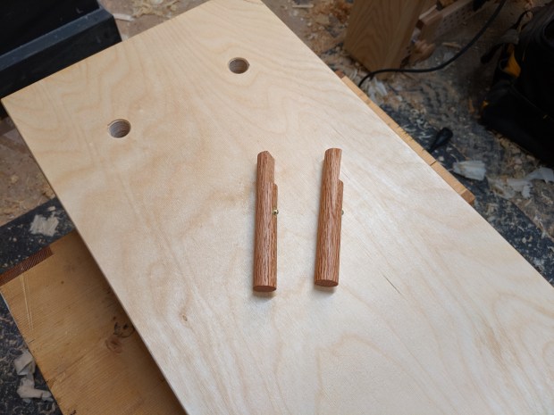
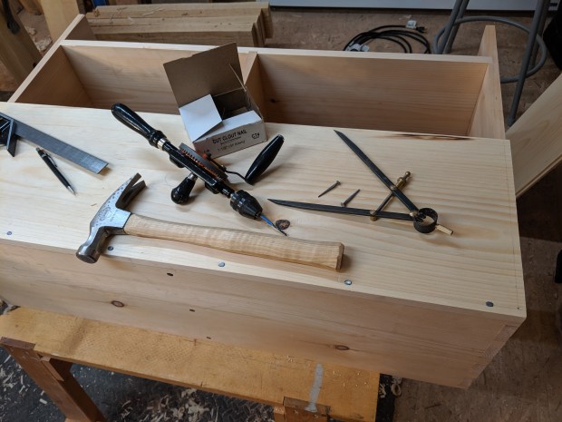
Don’t tell anyone, but I used the 18 gauge brad nailer to attach the runners and blocks.

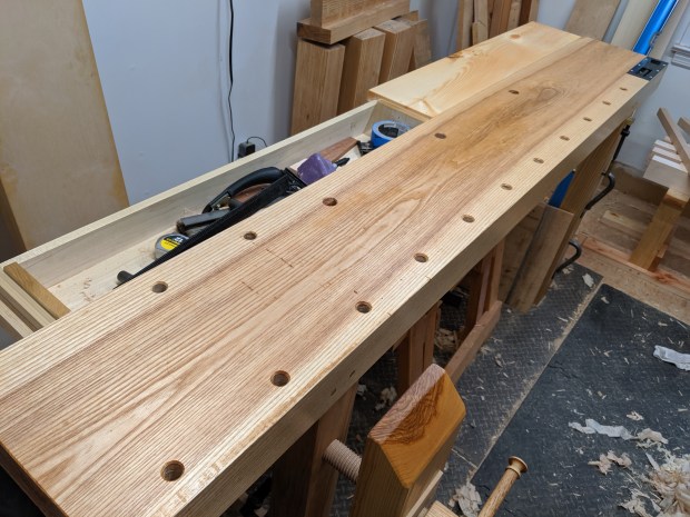
The ends of the tool tray are in plane with the workbench slab.  This was intentional, as originally I intended entirely replace the back wing with two tool trays.  But after working on the bench with the tool tray for a few days, it became very apparent that I needed at least part of the bench to be solid for the full 20″ of depth.

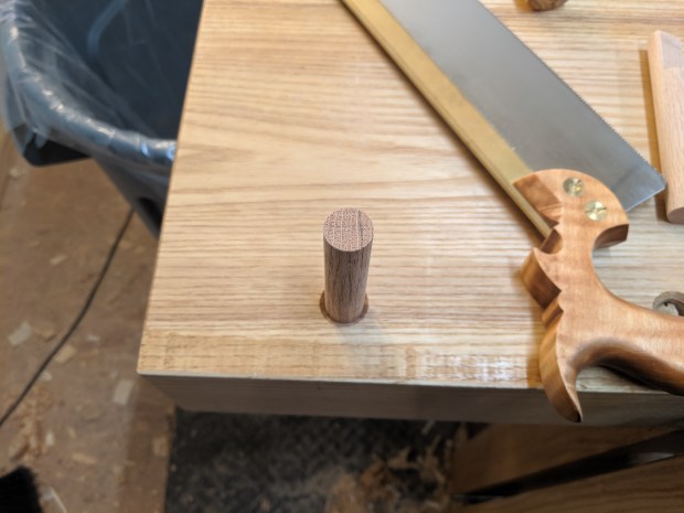
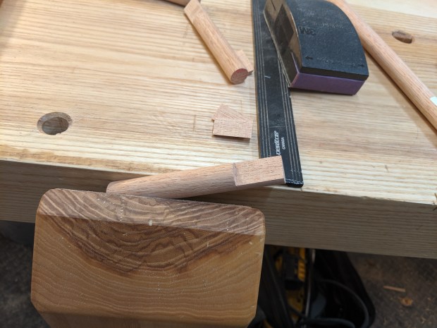
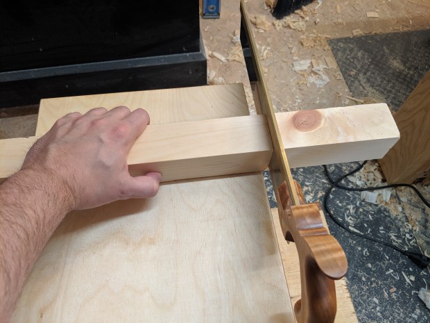
From 9 months or so of working on this bench, it’s become clear that the wing doesn’t need to be terribly stout.  It certainly doesn’t need to be 2″ ash reinforced with 2″ angle iron.  So instead I grabbed an otherwise somewhat useless 2″ pine off cut that’s lapped onto the posts.  There are a few wire brad nails acting like dowels to support the seam with the main slab and a couple more wire brads through the board into the posts to keep everything in place.  Net it, this board can move much more freely with seasonal expansion and contraction than the old wing could.  But it will be easily replaceable if I get neurotic and replace it with ash again (which, let’s face it, I definitely will).

IMG_20190728_090157.jpg

And the color match isn’t terrible, either.

For optics, but not functionality, I will probably nail a board to the end of the extension to bring it flush with the right end of the bench (and provide a bit more resistance to cupping, like a breadboard end).  Absolutely nothing ever happens all the way at that back corner.  It’s just to make it prettier.  I could do the same thing at the back right corner, but the end of the tray (which is flush with the bench top) is already in line with the last bench dog hole, so it’s not strictly necessary either.

I unfortunately can’t tell if the color match is getting better or worse with a second coat of Tung Oil.  Maybe I just have to open the blinds and let the sun shine in for a couple weeks.

IMG_20190801_091903.jpg

Or paint the whole thing black!

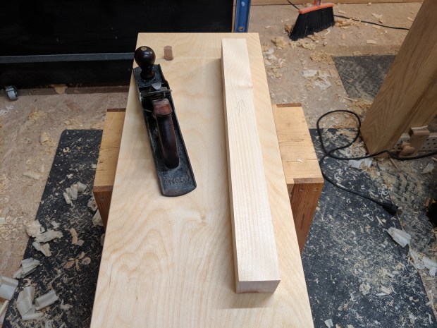
This is a good time to mention that 36.25″ is a bit too high for comfortable hand planing at my height (I’m 5’10”).  Even if it is better for sawing and chopping.  So I’ll eventually trim about 1″ off the ends of the legs.  Which is easier said than done, as the back legs are angled.

But I’ll give it a try and report back.

JPG

Budget Twin Screw (Moxon) Vise

A good twin screw vise can do many tasks.  When clamped to the edge of a bench top, it can be used as a proper face vise for dovetailing or other joinery.  Sitting free on a bench top, it can restrain an assembly for driving wedges or be a third hand for safely splitting tenons.  In a pinch, it can even take the place of a machinist vise for basic metalworking (although I would recommend vacuuming it off when you’re done, as metal shavings are anathema to woodworking tools).

But a good twin screw vise doesn’t have to cost a fortune.  I mean, it can, if that’s what you’re into (with wooden screws or prefab hardware and whatnot).  But it doesn’t have to.  In fact, all it really takes is about US$13 worth of home center hardware and some off cuts.

IMG_20190704_100838.jpg

That is some straight grain, eh?

There are two typical ways to make a vise screw work without a garter that attaches the movable jaw directly to the screw.  You can affix the screw to the back jaw, and turn a nut to sock down on the moving jaw.  Like the Benchcrafted Moxon Vise.  Or you can affix the nut to the back jaw and use the screw hub to sock down on the moving jaw.  Like the Lake Erie Moxon Vise.  For this, let’s do the latter.  There is a third way, which I’ll cover briefly below.

Start with the front jaw.  Now I am sure there are people who can use a brace and bit and drill a perfectly perpendicular hole.  But I can’t, so I used the drill press.  The screw should be relatively snug in the hole (phrasing?).  This threaded rod is about 3/4″ and a 3/4″ forstner bit was just tight enough.  Inset the holes at least 1 1/2″ from the ends of the front jaw for strength.  Some people elongate their holes to permit clamping irregular work.  I don’t.

IMG_20190704_101856.jpg

Also chamfer the holes.

It’s super important when making a twin screw vise that the holes line up.  So clamp the front jaw to the back jaw and use the same drill bit to transfer the center of the hole into the back jaw.  I should mention that the back jaw is about 4″ longer than the front jaw for some clearance each end when clamping to the bench.  Otherwise, the clamps get in the way of the work.

After you’ve bored the hole in the back jaw, put both jaws back together, insert the threaded rod, tighten up a nut on both sides of the jaws and trace around the nut on the back jaw with a marking knife.  Then chop down to the lines about three fourths of the height of the nut.  Repeat for the other nut and use a small bit of epoxy to affix the nuts to the back jaw.

IMG_20190704_104905.jpg

I do not know if the orientation matters for strength, but the epoxy will help.

Balance is an important part of any twin screw vise.  Even with the narrower front jaw, it’s likely the vise won’t balance itself with the front jaw hanging completely off the bench.  So I typically add an extension to the back jaw flush to the work surface.  It adds weight and stability and is a convenient place to put down your pencil or marking knife when cutting joints.  Glue should be all you need, but maybe add a screw or two through the inner jaw to make sure everything stays put long term.

IMG_20190704_150036.jpg

Some not-as-straight grain.

When the glue dries, you’ll have a functional vise.  There is something called a “rod coupling nut” which is really just an elongated nut.  You could use a couple of these as floating hubs and the vise would work just fine.  It wouldn’t be super comfortable (you’d have to turn the threaded rod by hand) and the nuts would wear into the front jaw over time, but it will hold.  Want proof?

IMG_20190704_172042.jpg

Proof.

You could also affix one of those rod coupling nuts to the end of each threaded rod and also be done.  But I like wooden screw hubs, so let’s do that.  Start with square stock and drill into the end of the hub.  I used the drill press, but you could do this by hand.  Just clamp the work across all faces to prevent splitting.

IMG_20190705_084133.jpg

Drill press vise for safety.

I think it took more time wedging underneath the benchtop to get it perfectly level in all directions than it took for the epoxy to set.  Be careful not to make too much of a mess, but excess epoxy can be used to reinforce the end grain of the hub (that wears against the face grain of the outer jaw).  When the epoxy was set, I drilled through the hub across the grain and pinned through the threaded rod with a 1/8″ steel rod (fixed with superglue).  Probably not necessary, but who knows what that zinc coating will do long term?

IMG_20190705_091822.jpg

If these were raw steel, the epoxy would be more than enough.

Then shape the hubs as you see fit.  I put a small chamfer on each corner of the hub for starts.  I have a feeling it’ll get down to roughly octagonal by the time it’s done.  I don’t like round hubs.

And that’s it.  Clamp it to your workbench and have at some joinery.  Maybe add a coat of penetrating oil finish to all surfaces other than the inside faces of the jaws.  I may glue some leather to the outer jaw to increase grip, but it’s not strictly necessary.


IMG_20190705_095947.jpg

That’s the steel pin through the handle.

If you’ve never made a vise before, this is a good way to figure it out.

I am, at this point, nearing US$100 into the low plywood workbench project, but it feel like it’s pretty much done.  I need to bore a few more holes in the bench top (and make a few more dogs) but that’s more planning than labor.

After undertaking this experiment, I have some thoughts.  But first, now that the vise is done, it’s time to make a little tool chest on this workbench!

Or, whatever.

JPG


Plywood Roman Workbench (Part 4)

Only by working on a low bench, like the plywood roman workbench, can you truly understand what they’re all about.  And after a week or so, I can definitely say there is something to finding the correct height for your body.  I’m just a shade over 5′ 10″ tall and I find 19 1/4″ to be the right height for saw benches.  And of the two low workbenches I’ve built in the past, one was 19 1/4″ and the other was 19 1/2″.  Both are very comfortable heights for me.  I build sitting benches within this range as well.  It’s the height from the ground to the bottom of my kneecap.

IMG_20190414_101920.jpg

Like this one.

But I’ve been working with the plywood Roman workbench propped up on my existing saw benches, which are already 19 1/4″ high.  That means the working height of the plywood Roman workbench is currently over 22″ high.  WAY too high for me to work comfortably.  I’m on my tiptoes most of the time, which is at least a good calf workout.  So let’s make some mini sawhorses out of construction grade 2×4’s to bring the slab to the correct working height.

IMG_20190701_170729.jpg

This is where we are going.

I always start with the math:

First, stand straight up with your feet flat on the floor and measure from the floor to the bottom of your kneecap with a tape measure. That is your overall target height (in my case, 19.25″).  Second, subtract the thickness of the plywood slab (2.875″ for me).  So I need to raise the slab 16.375″ (or 16 3/8″) off the ground.  Let’s round up to 16 1/2″ to make the math easy.

In the United States, construction lumber may be called “two by’s”, but it is really 1 1/2″ thick.  I dug through the stacks at the local Death Star and found two, 10 foot long 2×4’s in Douglas Fir that were relatively straight, relatively clear and relatively dry.  You could, in theory, get everything you need from a couple of eight footers, but why risk it?

Each mini sawhorse consists of six boards, all cut from 2×4’s:

  • Two foot boards (20″ long or so)
  • One top crossbeam (16″ long or so) – the freer of knots, the better
  • One lower stretcher (cut to fit, but around 14″ long)
  • Two vertical posts (total height of the sawhorse, minus 1″ [or 15.5″ in my case]) – these should come from the clearest sections of the lumber.  No knots at all, if possible.

Start by preparing the boards.  If your stock is straight and square and out of twist already, give it a quick smoothing pass and proceed to step two.  If not, and you’re feeling like a machinist, plane a reference face and square up a reference edge, then bring the opposite face and opposite edge into parallel.  I only had to take off about 1/16″ of total thickness on each board, so I’m sticking to the round numbers for purposes of this guide.

IMG_20190629_134111.jpg

Face mark, square mark, grain direction.  Every time.

Each post connects to the foot with a 1/2″ through tenon.  For the mortise, bore with a 1/2″ bit and pare to the lines, or chop with a chisel, up to you.  I chopped with a 1/2″ chisel to keep my skills up.  I also prefer to split my tenons, rather than saw down the cheeks.  But it is precarious work to split tenons without a vise.  After everything is fit, shorten each tenon to about 1/8″ less than the thickness of the foot board to give some clearance when it sits flat.

IMG_20190630_072302.jpg

One of two.

With one of the posts firmly seated into its foot, measure up to the total height of the finished sawhorse, minus 1″.  Cut off the post at this line and mark and use it to transfer the mark the other post (while in its mortise) .  This should ensure the two leg assembles are close to or exactly the same height.  Now, assemble each leg assembly with glue.  I drawbored these mortises and tenons too, but it’s not necessary.  Nails or even screws would be just fine to reinforce the joint.

IMG_20190630_105410.jpg

I think this shot was pre-drawboring.

The top beam attaches to the posts with dadoes that are inset from each end of the beam by the same distance the post is inset from the outside of the foot (in my case, 1″).  Determine the depth of the dadoes by subtracting from the overall thickness of the beam the height you need the beam to rise above the leg assemblies to get your final height (in my case, about 1/2″ dado depth).  Do your best to get tight dadoes, but they will be reinforced with dowels after the glue dries.  Err on the side of too narrow, as the construction lumber will compress.

IMG_20190630_180012.jpg

With dadoes seated.

The stretcher connects to the legs with lap joints.  You can use the finished top beam to transfer the distance between the shoulders of the lap joints.  I trimmed the lap joints to be flush with the outside of the posts, but that’s not strictly necessary.  I didn’t get a good picture of the lap joint process, but take a look here.

Glue the top beam onto the posts and seat the stretcher in place while the glue dries.  This will help keep everything square during glue up.  Then glue the stretcher to both the legs and the feet.  After the glue dried, I drove a pair of dowels through the top beam into the posts and couple of nails through the lap joint on the stretcher into the legs.  This should help with any wracking (front to back and side to side).

And then do it all over again.

IMG_20190704_062549.jpg

One is somewhat heavier than the other because they’re made from different 2×4’s.

I’ll be taking a slight detour in the next post to make some more workholding for future projects.

For now, Happy Birthday, America!

JPG


Plywood Roman Workbench (Part 3)

From my experience, a large portion of work holding when using a low workbench is sitting on the work.  But any good workbench for hand tool work needs at a minimum a planing stop for hand planing and a bench hook for sawing.  So let’s add both at the same time through a pair of bench dogs at one end of the newly-squared plywood slab.  Fair warning, the list of tools needed is going to increase from this point on.

IMG_20190626_131727.jpg

This is pretty much all you need for most woodworking.

Let’s begin with locating the dog holes.  In my experience, a single point planing stop will work without re-positioning the wood for boards up to about 5″ wide.  So on this bench, I spaced the dog holes at 5 1/2″ on center, equally spaced from each edge.   4″ from the end seems about right as well, so the dogs can be used as a bench hook in either direction.

I used a brace and bit to bore the holes, but a drill driver works just fine.  Use the bit that is the same size as the dowel you purchased (mine are 3/4″).  Do your best to bore the holes vertically, although if you’re going to err, hopefully err on the side of angled toward you.


IMG_20190626_080555.jpg

Two squares make boring true much easier.

Yes, this is a workbench, but don’t bore all the way through in one shot and break out the underside.  One day, you’ll probably flip the slab over and breakout is unsightly.  Instead, stop when the point of the bit just pokes through, then flip over the slab and finish the hole from the other direction.  That way, you’ll have clean exit holes on each face.  Then, break the edges of the hole with a countersink bit in a drill driver, a chamfer bit or roundover bit in a router, or with some coarse sandpaper.

IMG_20190626_084359.jpg

I prefer chamfer to roundover for dog holes.

Now, let’s make bench dogs.  You should feel free to purchase commercially made metal bench dogs and be done with it.  I like the brass ones from Lee Valley and use them on my main workbench.  But hand made bench dogs work great too.  Start with lengths of dowel that are 2″ longer than your slab is thick.  In my case, 5″.  Now, jam the dowel into the hole you just bored.  I had to use my main workbench because the dowel I purchased was apparently a bit undersized to the hole I bored.

IMG_20190626_075520.jpg

Nice, straight grain.

Orientation of the relief on the bench dog is critical to strength and grip.  Align the growth rings left to right, and mark a pencil line top to bottom that is about 1/4″ from the right side (left side, if you are left-handed).  Now, saw down that line, angled in about 2 degrees, to a cut depth of 1″ or so.  Then crosscut the waste away.  I used my leg vise but you can just clamp the dog to the slab or crosscut while the peg is vertical in the hole.  Be sure to ease the hard edges of the dog with some sandpaper of any medium grit.

IMG_20190626_075711.jpg

That’s literally all there is to it.

If your bench dog is snug in the dog hole but moves with light mallet taps, proceed to the next paragraph.  If the fit is too tight, thin the diameter of the dog a bit with some medium grit sandpaper, checking the fit as you go.  If the dogs fit loosely, like mine were, maybe buy some cheap brass bullet catches for cabinet doors or check out this Paul Sellers how-to on making wire springs for bench dogs (it starts at about the 11 minute mark).  If you use bullet catches, make sure to locate them in a place where they will catch when the dog is both up and down.  You’ll see what I mean.

Add a coat of Boiled Linseed Oil or Tung Oil (whatever you used for the bench top, honestly) and you’re done.

IMG_20190626_082808.jpg

Bullet catches are useful for a bunch of applications, honestly.

Once the oil finish is dry, pop in the dogs and have at some face and edge planing.

IMG_20190626_130413.jpg

One advantage to having two bench dogs instead of a single planing stop is you can crosscut boards using both pegs as a bench hook.  Like so:

IMG_20190626_130624.jpg

Goodbye, knot!

The slab now has all the workholding you’ll need to make two mini saw horses to replace the milk crates or buckets that you’ve been working on to this point.

I just finished up the prototype using just the slab with two bench dogs as my work surface.  I’m pleased enough with the design that I’ll replicate it for the second one.

IMG_20190701_170729.jpg

Basically 1/2 scale to full size saw horses.

But more on that later.

JPG


Fits and Starts, Part II

Life can sometimes feel like a series of unfinished woodworking projects.  I start with an idea and the best intentions, and something goes off the rails.  In this case, it’s the under-workbench cabinet from last year.  The case has been sitting around, taking up space in my workshop since before American Thanksgiving.  But, unable to get back to sleep around 330am, I decided to push it forward and nail on the tongue-and-groove case back.

IMG_20190522_070113.jpg

Is that the end of the tunnel or the train?

This was never meant to be fine furniture.  In fact, it’s sized to fit underneath my Stent Panel workbench.  But I’ve gotten used to keeping my saw benches there, so I’ve finally confirmed its new purpose as furniture.  Some 16″ hairpin legs will raise the deck to 36″.  The perfect height for a dry bar.

IMG_20190522_070126.jpg

Some detail on the T&G back boards.

The plan was always to dado in some shelves in one cubbyhole and add a door to the other.  I don’t think that’s the best use of the space if it’s not workshop storage.  Instead, I will add a drawer to the top of each cubbyhole and use the space beneath each drawer for book storage.  I probably should have done that stuff before nailing on the backboards, but when has patience ever been my first option?

IMG_20190522_070222.jpg

Probably overkill for something that won’t be mounted to a wall.

There is something profound about the process of laying out, drilling and driving nails.  I usually listen to music while woodworking, but I always forget to hit play with dividers in hand.  I guess it’s so I can hear the change in tone as the nail clears the pilot hole and bites the wood.

IMG_20190522_055300.jpg

Cut nails where they won’t be seen.  Die forged where they will.

It’s been a few months since I’ve cut any half blind dovetails.  They go quicker in pine, but tend to be a bit more ragged than in hardwoods.  I have a fine dovetail saw (20 tpi) that works well for those tasks.

It’s around here somewhere, anyway.

JPG

Getting it Together (the Short Version)

I had planned to write this whole post about wood movement and using tabletop anchors in finalizing the bathroom vanity project, but there is nothing I could say that Paul Sellers hasn’t said already (and better).

So, if you don’t know about wooden tabletop connectors, stop what you’re doing and go watch this Paul Sellers video.   After that, if you are so inclined, enjoy this picture of the undercarriage of the vanity.  Tabletop connectors not only hold the top on the vanity, but also anchor the entire assembly to the wall stud.

IMG_20190320_074131.jpg

Deep sinks are a PITA but worth it in the end.

Don’t forget to use brass fasteners in white oak.  Steel and white oak do not play nicely together.

JPG

Extreme Vanity

If a coherent philosophy exists in my woodworking, it’s this: “Why build when you can overbuild?”.  Or, perhaps, it’s “Could we? (not should we)?”.  Either way, it’s resulted in the most hilariously stout bathroom vanity of all time.

IMG_20190320_072451.jpg

Glamour shot just before the sinks go in.

The entire thing is quartersawn white oak.  The leg frames are entirely 8/4″ stock (final thickness of about 1 15/16″) and the top is 6/4″ stock (final thickness of just over 1 1/4″).  Everything is stub tenoned and drawbored with 3/8″ birch dowels and Titebond 1.  The long rails are even double drawbored front and back.

IMG_20190222_075158.jpg

It’s not a workbench, but it might as well be.

I chose to drawbore the mortise and tenon joints for two reasons.  First, there are no lengthwise lower stretchers, so it needed the extra rigidity.  Any lower shelf I make will just sit on top of the short rails of the leg frames.  But, more importantly, I don’t own any 60″ clamps so clamping this thing together would have been awkward and unreliable.

IMG_20190310_091644.jpg

Pre-assembly, pre-finish.

Drawboring also makes assembly less stressful.  You can move the constituent pieces individually and then assemble in situ at a leisurely pace. Sure: the assembled frame probably would have made it through the door from the hallway anyway.  But who knows (and why risk it)?

The net result is a piece of furniture with a frame that will never come apart.  Even if I want it to.

How the tabletop connects to the frame is a different story altogether, though.  More on that later.

JPG

Alternatives to Fighting

In progressing the standing desk build, I had to make a design choice regarding how to attach the back stretcher. But, more importantly, I had a practical choice to make. The angle of the back leg on each of the two frames is slightly off. Call it half a degree or so. Near the top of the assembly, there is no appreciable difference. 30″ or so down the legs, though, it’s nearly 3/16″ off.

I could, in theory, modify the cheek depth on one of the tenons and cant it very slightly to correct for this discrepancy. Or I could just run the stretcher near the top where the bag legs are, for all practical purposes, parallel. And if I’m doing that, why not in my impatience just lap a dovetail?

Because of course dovetails.

Half-lapped dovetails are an interesting joint. I personally find them aesthetically displeasing, even when executed perfectly. But they provide a mechanical resistance against tensile force that in other joints would require some sort of fastener (dowels, screws or bolts). And, like the comparable joints (mortise and tenon, half lap joint), they have significant long grain to long grain glue surface for maximum strength.

Plus, I find them rather easy to cut once you dial in the compound angle.

Ugly or not, this particular joint is not only on the back of the assembly, so I don’t have to every look at it again. Plus, it will be painted. So I’m happy with the choice.

Now I just have to make the top.

Have I mentioned that Eastern White Pine is just the best? Because it is.

JPG

Palate Cleanser

With the bathroom renovation fully underway, I couldn’t put off building the vanity any longer. Almost two years ago, I selected the design to generally rip off. Shortly thereafter, I purchased who knows how many board feet of 8/4 quartersawn white oak, which then sat in my workshop to acclimate for many months before dimensioning.

It’s been so long, my new workbench was still in big room..

White Oak can be very beautiful and (being both waterproof and tough) it is perfect for applications like bathroom vanities. Hard Maple works well too. But unless it’s air dried, White Oak is just too damned hard to work with hand tools alone. Based on how tough it is (and the way it warped when acclimating in the shop), I assume this stock is kiln dried. So I didn’t even bother trying to chop the mortises by hand. Instead, I utilized the drill press like a mortising machine and pared each mortise to width with a chisel. I also squared the corners, because effort.

Before and after.

The tenons were no peach either. I typically saw tenon shoulders and then split the tenons cheeks (rather than saw them). A router plane then pares down the cheeks to get a piston fit. This approach works pretty well, even in kiln dried White Oak, as long as I don’t take too much of a bite with the router plane. But fine-tuning the tenon shoulders (i.e., end grain) with a shoulder plane is basically impossible. If I don’t saw perfectly to the line, it’s chisel paring or bust.

So after getting through the joinery on both end frames, I was ready for a change. Back to the Eastern White Pine standing desk I’m leisurely making for my home office! If you’ve been reading for any amount of time, you know that I prefer to torture myself with angled back legs and this desk build is no exception.

Fluffy and delightful.

Why Eastern White Pine for desk, you may ask? Well, it’s my experience that a softer wood with a bit of flex is better in the long run for hands and elbows. I’ve been working on a quartersawn red oak desk for about five years now and I’m pretty sure I have arthritis in one elbow because of it. I’ve taken to using gel rests for both keyboard and mouse, but they don’t do anything to make up for the lack of flex.

It’s always a boon to make it through an assembly with no broken pegs.

These frames are only 34″ high overall (and will likely be down to 33.5″ when the feet are leveled). Add in two inches of bearer and two more inches of tabletop, and perhaps 3/8 of felt furniture pad, it’s still only about 38″ high. At just a bit over 5’10”, a perfect standing desk for me is about 40″ high. So where am I getting the rest of the height? From my ventilated laptop stand, of course!

The final desk won’t be quite as long or as wide as my current desk. I don’t work from home nearly as much as I used to, so there is just no good reason for a 76″ x 30″ desk. It takes up too much space. Something more like 60″ x 20″ will be plenty of real estate and will free up a fair amount of floor space.

But this new standing desk will make my current office chair pretty useless, so I need to find a decent 30″ stool with a backrest.

Find or make, I guess.

JPG

Branching Out

I’ve been woodworking for about six years total.  Four or so have been hand tool-focused.  It’s hard to admit, but I never really went hand tool only, as I rely pretty heavily on my thickness planer.  I also use a drill press from time to time, because I have one.  And it came in handy recently, as I forayed into some more basic metalworking.

IMG_20181103_120735.jpg

For me, this is complicated metalwork.

After working at the new workbench for a couple of months, it became rather clear that the connection between the main slab and the extension needed shoring up.  Three posts and some 4″ lengths of angle iron at random intervals weren’t doing the trick.  It needed something more substantial.

I found myself at the home center at 601am on a Saturday (I was actually there for cleaning products), and it seemed they had freshly restocked the angle iron.  I had cobalt bits and a new countersink, so I figured, “why not?”.

IMG_20181103_133941.jpg

Not even I worried about clocking these screws.

Drilling through 1/8″ mild steel is not too bad (although the squiggly shavings can be sharp!).  And countersinking is messy and loud, if satisfying.  The only hard part about the entire endeavor was lining up the holes in the angle iron to not interfere with the planing stop or holdfast holes.

Now two lengths of 24″ angle iron, with screws at 1.5″ and 8″ from each end, reinforce the joint between the slab and the extension.  They also added a couple of lbs. to the workbench, which can’t be overstated.  Although I’m keeping the workbench shelf-less, I am in fact going to add a back stretcher between the angled back legs to increase the heft overall.

Speaking of which, I added some extensions to the back of the angled legs.  Now the footprint of the legs nearly matches the depth of the bench top, which makes the bench more stable when traversing or using a shooting board.  The extensions also, conveniently, create a ledge for the back stretcher to ride on (meaning I can get away with not gluing the lap-jointed stretcher in place).

IMG_20181108_152929.jpg

Hide glue and 3/8 lag bolts ensure it won’t ever move.

My next project is a cabinet for under the bench, which will store clamps, fasteners and other odds and ends that I use enough to keep them close at hand, but not so often that they should be in my tool chest.  I’m purposely building it in a way that can be converted to a wall cabinet if the mood ever seizes me.

Stay tuned.

JPG