Another year has passed. As is my heathen wont, I went to bed early last night, stone sober and well hydrated, and hit the shop early this morning. I like to begin each year on my own terms. And then ride out the downhill trajectory from there.
In advance of my regular January vacation, I’ve been making a “gentleman’s tool chest” for a core set of hand tools. Now I’m no gentleman (or so I’ve been told), but as I understand it, the “gentleman” refers simultaneously to (x) a non-professional woodworker and (y) the smaller set of tools a non-professional joiner or cabinetmaker would have in their chest. So maybe I am a gentleman.
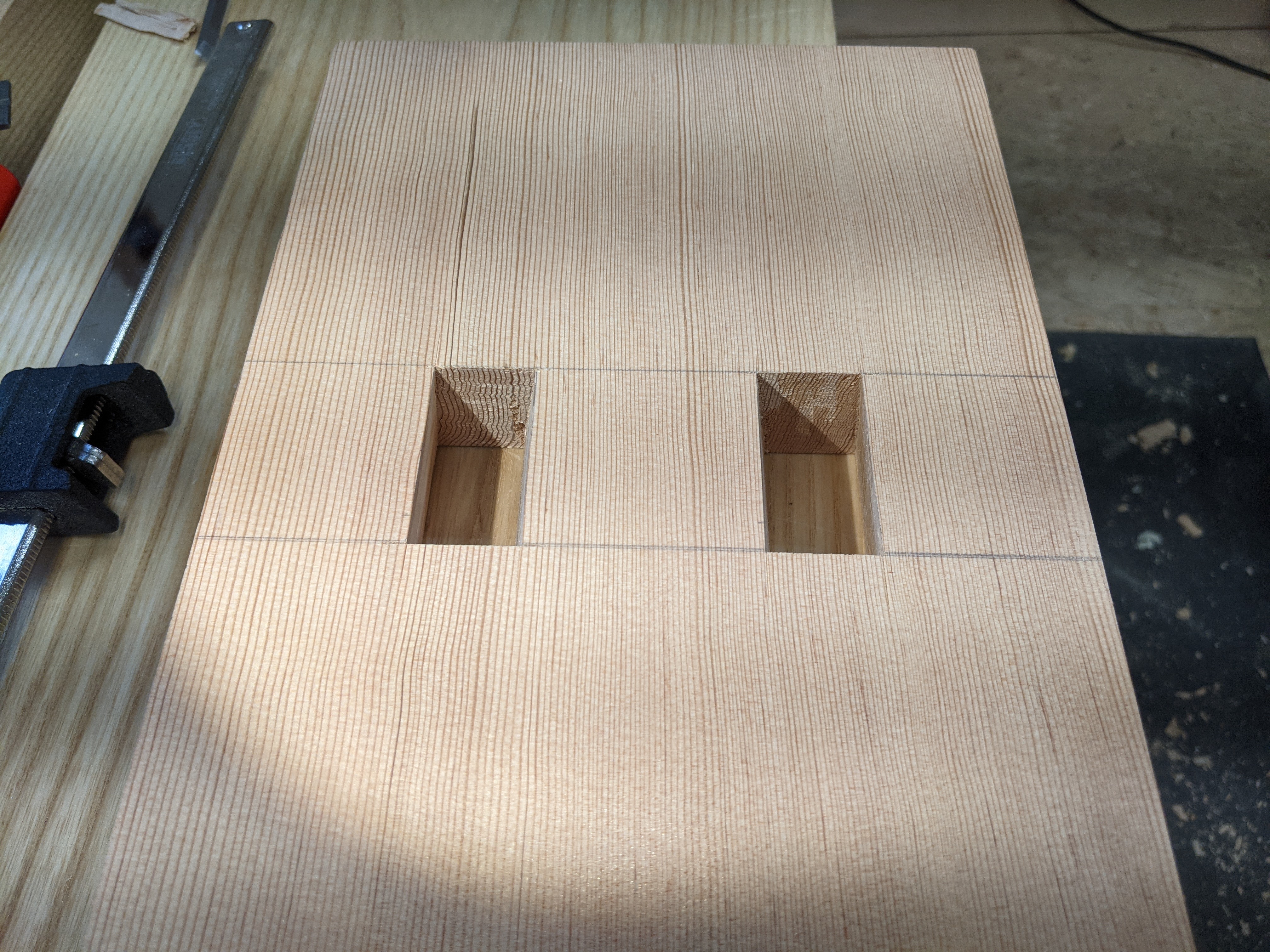
This particular tool chest is a modest 25″ long, 11″ deep and 11″ high and will have 2 sliding tills. The planes and sharpening gear are french fit into the tool well and there won’t be too much lose gear rattling around. It’s also intended to be a general around-the-house toolbox holding my nicest spare tools so it will move around a fair bit.

In any tool storage build, like in life, there are compromises. For example, there is not any room for joinery saws in this chest, but I have modified a 10 tpi rip saw (it crosscuts too) and a 6 tpi rip saw to have shorter plates. I say modified; I cutoff about 5 inches from the toe of each saw with an angle grinder and filed off the burrs. The shorter plates are stiff enough for precise sawing as needed (and everything gets cleaned up with chisel or router plane anyway).

The full kit this holds is as follows:
- Planes: No. 5 jack plane, No. 3 smoothing plane, Low-angle block plane, small router plane
- Saws: 10 tpi rip cut panel saw (18″ plate): 6 tpi rip cut panel saw (18″ plate)
- Chisels: 1/4, 1/2, 3/4, 1 inch bench chisels, carver’s mallet
- Marking and measuring: 12″ combination square, 8″ machinist square, wheel marking gauge, 12 foot tape measure, folding marking knife, mechanical pencils
- Boring: Two jaw, short sweep brace, plus hex adapter, large diameter adjustable auger bit, drill bit set, hand countersink
- Sharpening: 120, 220, 1200 grit diamond plates, side clamp honing guide and setup block, plus glass cleaner and jojoba oil
- Miscellaneous: Warrington-pattern hammer, slotted and phillips screwdrivers, cork sanding block, foam ear plugs (lots of these)
I’m sure there is something I’m forgetting (I can supplement this later), but I find the above set of tools is everything one needs for general woodworking projects that aren’t intended to be the finest furniture. I can take rough lumber to dimension with these tools and do crisp joinery by hand without too much fuss. I will likely make or purchase a medium router plane to fit this chest, as well as a set of wooden winding sticks and a wooden straightedge.
As I write this, the second till is glued and nailed and drying in the shop. So that means only one thing: it’s lid time.
And that’s the point at which every tool chest build starts to get tedious.
Happy New Year, everyone!
JPG